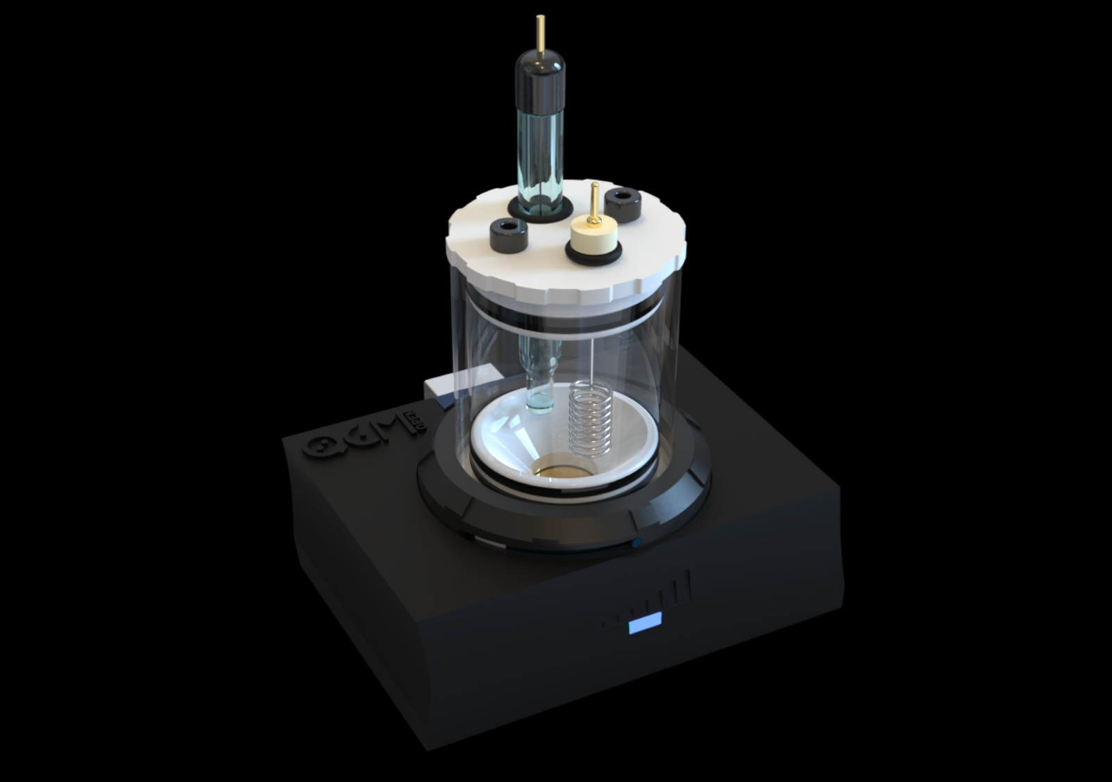

openQCM has a temperature sensor with high accuracy based on thermistor and Arduino. The Quartz Crystal Microbalance accuracy depends on temperature.
The openQCM temperature sensor is physically placed into the Arduino Micro shield, so it actually measures the openQCM device temperature. The ambient temperature is a key parameter in the development of a QCM because the quartz resonator frequency is partially affected by the variations in temperature.
At first we choose an RTD Resistance to Temperature Detector for measuring the temperature. But the test results were not good at all ! We were able to measure the temperature with a poor resolution of about 2°C. Although I had processed the signal I could not do the magic, definitely !
Finally we found a very easy solution, by replacing the RTD with a Thermistor temperature sensor without changing the openQCM shield circuit. The thermistor temperature sensor has a resolution of about 0.2 °C
Thermistor Temperature Sensor
The thermistor is a special kind of resistor whose resistance varies strongly with the temperature. It is common used as a temperature sensor. Because the temperature measurement is related to the thermistor resistance, we have to measure the resistance. Arduino board does not have a built-in resistance sensor. We have to convert the thermistor resistance in a voltage and measure the voltage via the Arduino analog pin. Finally we calculate the temperature using the Steinhart–Hart equation which described the thermistor resistance – temperature curve.
The Voltage Divider Circuit
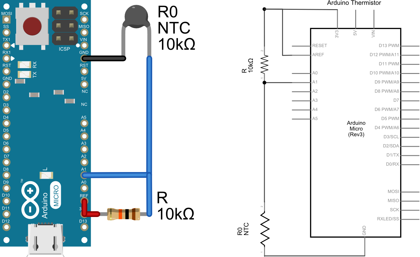
To the purpose of measuring the voltage we connect in series the thermistor to another fixed resistor R in a voltage divider circuit. The variable thermistor resistance is labeled as R0. We select a thermistor with a resistance of 10 KΩ at 25°C and the fixed resistance of 10 kΩ. The input voltage Vcc of the voltage divider circuit is connected to the Arduino Micro 3V, which provides a 3.3 volt supply generated by the on board regulator with a maximum current draw of 50 mA. The 3V pin is connected to the AREF pin because we need to change the upper reference of the analog input range.
Say the output voltage V0, the power supply Vcc, the variable thermistor resistance R0 and the fixed resistance R, the output voltage is given by:
V_0= (V_{cc} \cdot R_0) / (R_0 + R)
The output voltage is connected to the Arduino analog input pin A1. Arduino Micro provides a 10-bit ADC Analog to Digital Converter, which means that the output voltage is converted in a number between 0 and 1023. Say A1 the ADC value measured by Arduino Micro then the output voltage is given by:
V_0 = A1 \cdot V_{cc} / 1023
By combining the previous equations we have:
V_{cc} \cdot R_0 / (R_0 + R) = A1 \cdot V_{cc}/1023 \Rightarrow R_0 / (R_0 + R) = A1 / 1023
That’ s really interesting ! The thermistor resistance R0 is independent by the supply voltage Vcc
What we need for temperature measurement is the thermistor variable resistance R0. Using the previous equation and some math we have:
R_0 = A1 \cdot R / (1023 - A1)
The resistance measurement depends on the ADC Arduino A1, the fixed resistor R in the voltage divider, and the ADC resolution 1023.
Tip & Tricks How To Improve the Temperature Measure
We used some tricks to improve the temperature measurement with a thermistor.
Supply Voltage I have shown before that the thermistor resistance measurement does not depends on the supply voltage Vcc. So, why do we connect Vcc to the Arduino 3V pin rather than 5V pin ? The 5V pin supply comes from your computer USB and it is used to power Arduino and a lot of other stuff on the board. So it is noisy definitely ! Instead the 3V pin is much more stable because it goes through a secondary regulator stage. In addition, as I will explain at the end of the post, the temperature accuracy depends on the supply voltage. The lower is the supply voltage the better is the temperature accuracy.
ADC The Arduino board has a 10-bit ADC resolution. As far as I know, the easiest way to improve the ADC resolution is to acquire multiple samples and take the average. I suggest to average over 10 samples to smooth the ADC data.
Thermistor Tolerance Every passive electronic component has a nominal value and a tolerance, which is the relative error of the nominal value. I suggest to choose a 10 KΩ thermistor with a tolerance of 1%, which means that the resistance has an error of 100 ohm @25° C . At 25° C a difference of 450 ohm corresponds to about 1°C, so a tolerance of 1% corresponds to temperature error of about 0.2 °C, which is good enough for this application!
Converting the Resistance to Temperature
We are developing a temperature sensor, so the last step is to convert the resistance in a temperature measurement. The thermistor has a quite complicated relation between resistance and temperature, typically you can use the resistance to temperature conversion tables. Instead I suggest to use the Steinhart-Hart equation (aka B or β parameter equation) which is a good approximation of the resistance to temperature relation:
1/T = 1/T_0 + 1/B \cdot ln (R/R_0)
where R is the thermistor resistance at the generic tempearature T, R0 is the resistance at T0 = 25° C and B is a parameter depending on the thermistor. The B value is typically between 3000 – 4000. The equation depends on three parameters (R0, TO and B) which you could find in any thermistor datasheet. Although this is an approximation, it is good enough in the temperature range of application and it is easier to implement respect to a lookup table.
The Arduino Code
The temperature measurement is implemented in the Arduino code via the getTemperature function. The code is based on that wrote by Lady Ada on the Adafruit website.
Here my piece of sketch for the temperature using a thermistor with Arduino:
[code language=”cpp”]
// Thermistor pin
#define THERMISTORPIN A1
// resistance at 25 degrees C
#define THERMISTORNOMINAL 10000
// temp. for nominal resistance (almost always 25 C)
#define TEMPERATURENOMINAL 25
// how many samples to take and average
#define NUMSAMPLES 10
// The beta coefficient of the thermistor (usually 3000-4000)
#define BCOEFFICIENT 3950
// the value of the ‘other’ resistor
#define SERIESRESISTOR 10000
// measure temperature
int getTemperature(void){
int i;
float average;
int samples[NUMSAMPLES];
float thermistorResistance;
int Temperature;
// acquire N samples
for (i=0; i< NUMSAMPLES; i++) {
samples[i] = analogRead(THERMISTORPIN);
delay(10);
}
// average all the samples out
average = 0;
for (i=0; i< NUMSAMPLES; i++) {
average += samples[i];
}
average /= NUMSAMPLES;
// convert the value to resistance
thermistorResistance = average * SERIESRESISTOR / (1023 – average);
float steinhart;
steinhart = thermistorResistance / THERMISTORNOMINAL; // (R/Ro)
steinhart = log(steinhart); // ln(R/Ro)
steinhart /= BCOEFFICIENT; // 1/B * ln(R/Ro)
steinhart += 1.0 / (TEMPERATURENOMINAL + 273.15); // + (1/To)
steinhart = 1.0 / steinhart; // Invert
steinhart -= 273.15; // convert to C
// decimal value
Temperature = steinhart * 10;
return(Temperature);
}
[/code]
Thermistor vs RTD Temperature sensor
I have shown before that using a thermistor of 10 KΩ with a tolerance of 1% you can measure the temperature with a resolution of about 0.25 °C. Why the thermistor is better than an RTD (Resistance to Temperature Sensor) as temperature sensor for this specific application ?
Both the sensors measures the temperature by measuring their variation in resistance. The voltage divider circuit is used for both sensors. In the first electronic design of openQCM we choose the RTD PT100 sensor manufactor Jumo part number PCS_1.1503.1 with nominal value of 100 Ω and a tolerance of 0.12 %. The RTD PT100 sensor is strongly affected by overheating. The recommended measuring current is i_min = 1.0 mA and the maximum current is i_max = 7.0 mA. We need to choose the series fixed resistor in order to fulfill this requirement. But the lower is the current the lower is the resolution of RTD resistor measurement. In order to strike a balance between these requirements, I choose the series resistor R = 400 ohm which determines a current of about 6.5 mA in the voltage divider circuit.
Say Vcc the supply voltage, R the fixed series resistance and R0 the variable RTD resistance, one has at 25° C a current:
i = V_{cc}/(R + R_0) = 3.3 V / (400 + 100) \Omega = 6.5 mA
The standard platinum RTD resistance to temperature conversion table is available for example at this link . Consider the RTD resistance values at 0°C and 50°C :
R_0(50^{\circ} C ) = 119.4 \Omega \qquad R_0(0 ^{\circ} C ) = 100</p> <p>\Omega
The 50° C temperature variation corresponds to a voltage variation dV given by;
dV = V_0(50^{\circ} C) - V_0(0^{\circ} C) =
= V_{cc} \cdot R_0(50^{\circ} C) / (R + R_0(50^{\circ} C) ) - V_{cc} \cdot R_0(0^{\circ} C) / (R + R_0(0^{\circ} C))
Say Vcc = 3.3 V and R = 400 Ω we would measure a voltage variation:
dV = 0.758 V - 0.660V = 0.1 V
By using the Arduino 10-bit ADC the voltage variation dV corresponds to 1023 * 0.1 / 3.3 = 31 divisions. Finally, the accuracy dT of the RTD temperature sensor is given by:
dT = T / \# divisions = 50^{\circ} C/31 div = 1.6 ^{\circ} C
The RTD temperature sensor has an accuracy of 1.6 °C which is by far too low for this kind of application !
Do the same for the thermistor ! By using the standard 10 kΩ thermistor resistance to temperature table, one has:
R_0(50^{\circ} C ) = 10.97 k\Omega \qquad R_0(0 ^{\circ} C ) = 29.49k\Omega
If Vcc = 3.3 V and the fixed series resistor is R = 10 kΩ, the 50° C temperature variation corresponds to a voltage variation of:
dV = 0.74 V
The number of ADC divisions is given by:
\# divisions = 1023 \cdot 0.74 V/ 3.3 V = 229
The temperature accuracy is:
dT = 50 ^{\circ}C / 229 div = 0.2 ^{\circ}C
The thermistor sensor has a temperature accuracy of about 0.2 °C in the temperature range of interest for openQCM. The thermistor accuracy is much better than the RTD one and it is good enough for this application definitely !
Reference and Further Reading
- Thermistor via wikipedia http://en.wikipedia.org/wiki/Thermistor
- Using a Thermistor via Adafruit Adafruit https://learn.adafruit.com/thermistor/using-a-thermistor#how-precise-is-the-reading
thanks to LADY ADA for the great tutorials ! - RTD temperature sensor module http://openenergymonitor.org/emon/buildingblocks/rtd-temperature-sensing
thanks to Trystan Lea at the open source project OpenEnergyMonitor
cheers
marco