

openQCM is the fully open source quartz crystal microbalance project with an Arduino electronic board inside its heart
openQCM is the fully open source quartz crystal microbalance which uses Arduino as microcontroller board. I am sure that anyone in the open source movement have heard about Arduino, which is an amazing open-source electronics prototyping platform based on a simple hardware and software language.
When we started the openQCM project we have firmly decided to realize a fully open source hardware for scientific applications. In this sense our project and Arduino share the same “philosophy”, the idea to realize a product accessible to anyone, scientists, hobbist, geek, so can anyone can control and develop their own technology. The decision to choose Arduino as microcontroller board was simply natural.
In this post I will present the openQCM electronic working scheme and the code for programming the Arduino board.
Hardware
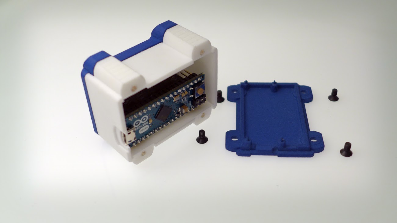
openQCM hardware is mainly made of three components:
- Arduino Micro board
- QCM Arduino shield
- Temperature Sensor
Arduino Micro
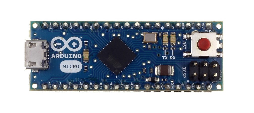
Arduino Micro is the microcontroller board at the heart of openQCM. Arduino Micro is a small board suited for compact device design. It is based on the ATmega32u4 microcontroller with 8-bit CPU operating at 16 MHz maximum frequency. The most important technical features of Arduino Micro for the openQCM project are:
- Operating Voltage @5 VDC via micro USB connection
- Clock speed @ 16 MHz
- DC Current for 3.3V Pin 50 mA
- Analog input channel
Thanks to these features, openQCM is able to be powered simply via USB connection, measure the quartz crystal frequency by hacking the Arduino timer interrupts, supply power to the quartz crystal oscillator driver and read the analog temperature sensor. openQCM with Arduino inside is an highly sensitive and smart sensor definitely, am I right ?
QCM Arduino Shield
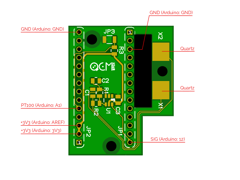
openQCM has a custom designed quartz crystal microbalance shield compatible with Arduino Micro. It represents the main electronic module of openQCM, what makes openQCM a proper scientific instruments. We have designed the openQCM Arduino shield in order to easy connect the Arduino board to the shield. That’s simple as to take a coffee !
The openQCM shield implements a quartz crystal oscillator driver in Pierce oscillator configuration. The driver circuit is designed for crystal oscillator applications in a wide range of frequency. We have optimized the design in order to enhancing the frequency stability and power consumption
Furthermore the openQCM shield has an embedded sensor to measure the temperature of the device. This is an important feature to check the thermal stabilization of the device. So by cross-checking the frequency vs temperature data provides useful informations on your ongoing experiments.
Temperature Sensor
The temperature sensor is a PT100 resistance temperature detector RTD. The RTD resistance is directly related to the temperature via a predictable linear relation.
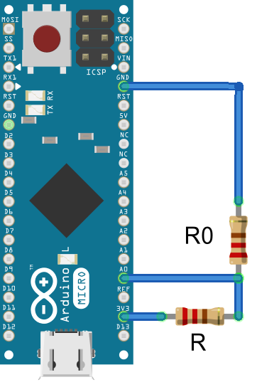
How to measure the resistance variation of the RTD temperature sensor ? PT100 is inserted in a voltage divider linear circuit. By measuring the voltage via the Arduino analog pin one can calculate the PT100 resistance. In the circuit R0 is the Pt100 resistance, R is a 100 ohm resistor, Vcc is the Arduino 3.3 V outup pin and V0 is the voltage measured via the analog pin A0. So for the Ohm’s law the resistance R0 of the Pt100 rtd temperature sensor is given by
$latex R_0= \frac{V_0}{V_{cc} – V_0}R$
Arduino Sketch step-by-step
The openQCM Arduino skecth is available on github repository openQCM-Arduino
The FreqCount Library for Measuring Frequency
openQCM-Arduino uses the external library FreqCount, which measures the frequency of a digital signal by counting the number of pulses during a fixed time. This awesome library was cooked by Paul Stoffregen at PJRC. He made a great work definitely, massive congrats ! By hacking the Arduino timer interrupts the library uses the 16 MHz Arduino clock to count the number of pulses of a TTL signal in a fixed gate time interval. The signal coming from the quartz crystal oscillator of openQCM Arduino shield is a TTL compatible signal and by fixing the gate time interval at 1 second it is possible to measure the quartz crystal frequency with a 1 Hz resolution.
The frequency measure is implemented in the following instructions:
[code language=”cpp”]
// fixed "gate interval" time for counting cycles 1000ms
#define GATE 1000
…
void setup(){
…
// Begin frequency counting
FreqCount.begin(GATE);
}
void loop(){
// check if a new measure is available
if (FreqCount.available())
{
// measure frequency
count = FreqCount.read();
…
}
[/code]
For more information on the FreqCount library follow this link by Paul Stoffregen at PJRC. The FreqCount library is also available on github repo. For advanced notes about hacking the arduino timer interrups follow the instructable by Amanda Ghassaei
Temperature Measure
The temperature measure using PT100 resistance to temperature sensor is implemented in the function getTemperature()
[code language=”cpp”]
int getTemperature(void){
// TODO calibration
const int calib = – 18;
// resistor in voltage divider circuit
const int R_ref = 100;
// voltage reference in voltage divider circuit
const double V_ref = 3.3;
double volt = map_value(analogRead(1), 0, 1023, 0, V_ref );
double alpha = volt/V_ref;
double resistance = (alpha/(1 – alpha))*R_ref;
// PT100 linear relation between resistance and temperature
// t(°C) = 2,596*R(ohm) – 259,8
// Resistance range (100, 140) OHM
int Temperature = int ( 2.596 * resistance – 259.8 );
// TODO PT100 calibration
Temperature = Temperature + calib;
return(Temperature);
}
[/code]
Data Serial Communication
The data serial communications protocol is implemented in the function dataPrint
[code language=”cpp”]
// print data to serial port
void dataPrint(unsigned long Count, int Temperature){
Serial.print("RAWMONITOR");
Serial.print(Count);
Serial.print("_");
Serial.print(Temperature);
Serial.write(255);
}
[/code]
At the beginning the function prints the string “RAWMONITOR” in order to communicate that a data string is coming. In this way you can ignore any spurious message at the serial port. Then the function prints the data string and finally write the byte 255 which set the end of data transfer.
cheers
mm


2 thoughts on “openQCM has Arduino inside at heart”
please share its circuit diagram and source coading for the arduino uno
Hi, sorry for the late reply.
You can download the schematics in KiCAD here
http://openqcm.com/shared/electronic/openQCM_Electronic-1_2.zip
You can download the source code for Arduino here
https://github.com/openQCM/openQCM-Arduino